Pozzi Leopoldo RCR EOP - heat recovery system
General info: RHeX & RCR with continuous effluent streams
Application
- Home /
- application /
- General info: RHeX & RCR with continuous effluent streams
01. BEST PRACTICE FOR EXCHANGER CONNECTION
Below we will provide a set of guidelines regarding the proper connection of the RCR heat recovery exchangers to continuous machines.
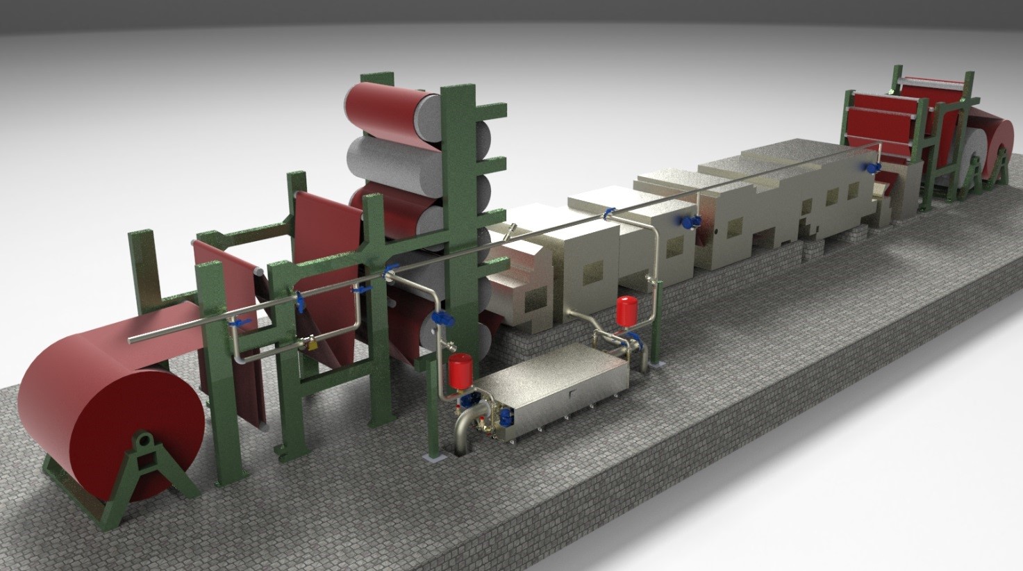
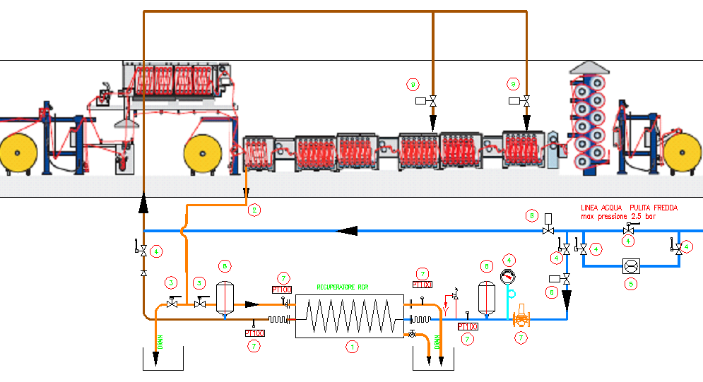
The diagram above illustrates, in three dimensions, a typical application of RCR heat exchanger on a continuous washing line while the drawing below summarizes the correct applied schematics.
01.01 Discharges collection with more than one effluent point
Most machines on the market have an internal hydraulic circuit that is arranged for the supply of water in counter-current, which means that the clean water is generally supplied to that side of the machine which provides the output of the clean fabric, while discharges are collected towards the fabric inlet where the bath is definitely more contaminated.
It is advisable, therefore, that the heat exchanger is positioned as close as possible to the point of withdrawal of the contaminated bath in order to avoid long pipe-works that may
· Create counter-pressure points on the drain overflow of the machine;
· Introduce unnecessary loss of temperature due to heat loss.
In some cases, however, within a single machine, the countercurrent tank groups may be more than one, depending on the specific task that each of these groups plays in the total economy of the machine.
In the case of multiple discharges from the machine, when these have very different temperatures among each other, it should be kept in mind that it is a good rule to leave the recovery system divided in several elements, mounting smaller exchangers on each section, each adequate to the individual local flow-rate.
Mixing of two or more streams tends, in fact, to average (lowering) the temperatures.
The multiple set-ups have more efficiency of heat transfer since the negative effects of the reduction of available temperature difference for heat exchange will be eliminated.
It should be kept in mind that the amount of heat transferred through a heat exchanger is proportional to:
Q = KxSxDT
where
Q = quantity of heat exchanged
K = heat transfer coefficient (dependent on the design of the heat exchanger)
S = surface area of heat exchange
DT = temperature difference between the water to be cooled and the one to be heated .
Therefore, the greater the temperature difference which is maintained between the two circuits, the higher the amount of heat recovered.
It is obvious that any mixing between two streams at different temperature necessarily tends to lower the maximum temperature value of the effluent and therefore reduces the quantity of exchanged heat.
01.02 The standard single exchanger application in detail
A: Input wastewater circuit
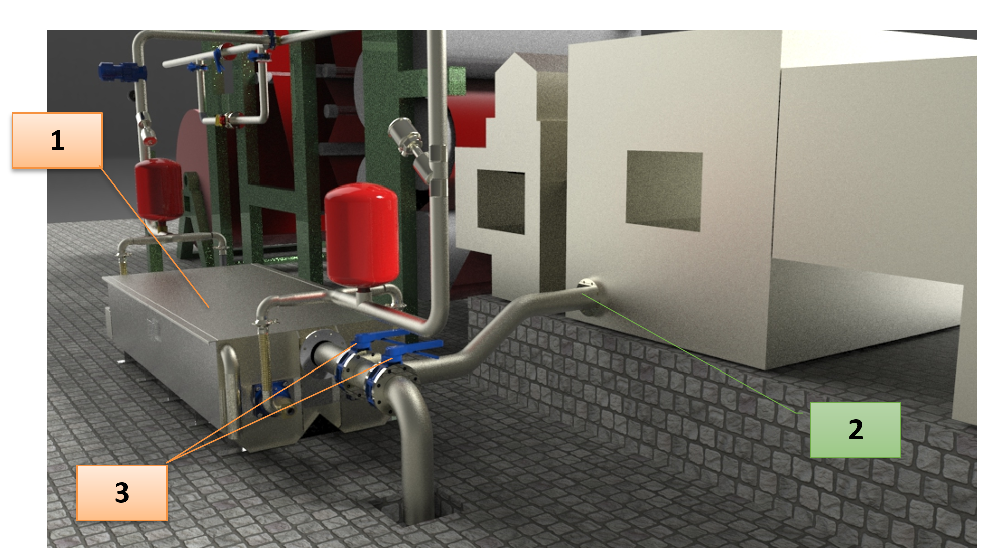
Following the picture above, zoomed in this case, of the hydraulic connections of the heat exchanger (1), we can examine the various components.
The heat exchanger is normally fed by gravity from the machine (2), auxiliary pumps are not necessary as the maximum head loss developed along the length of the heat exchanger is only equal to a few inches of water column. Note however that the machine discharge pipe should not be restricted or unduly bent so as not to create extra pressure losses
A couple of butterfly valves (3) can be used to divert the flow toward the exchanger or to the drain (useful during maintenance times).
In almost all cases of application, you do not need the installation of in-line filters on the exhaust piping of the machine.
In fact, the strong turbulence caused by the rotating heat exchangers keeps the mechanical contamination material in suspension.
Only in some special environments, where the elements of contamination tend to sink to the bottom of the tank because of their specific gravity or the presence of particular binders, we recommend the use of gravity-fed coarse pre-filters.
These are mostly useful for dilating the periods of maintenance cleaning of the heat exchanger, removing the coarser part of the contaminants and thus reducing the volume that could be accumulated in the tank.
B: Water feeding circuit
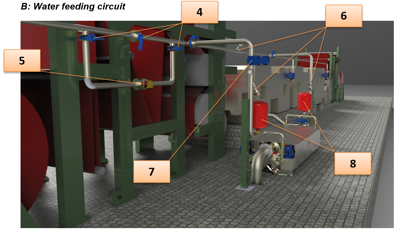
It is good practice to install a flow meter (5) on the input circuit of the water: it can be used for controlling or adjusting the flow-rate and the performance of the heat exchanger.
A group of valves (4) will create a bypass circuit for the same in case of maintenance needs.
Another group of three valves (6) will provide the necessary by-pass to the connection of the heat exchanger that can be put in line or isolated according to the needs of the plant. (for example switching from cold to preheated water inlet)
C: Inlet water pressure
It is important that the pressure of the water inlet in the heat exchanger is kept lower than three bars. An accurate control of pressure, in fact, makes it possible to greatly extend the life of the heat exchanger: over-pressures could result in cracks at the welds of the rotating discs of the heat exchanger.
Unless with absolute certainty you know that the inlet pressure never exceeds three bars, you will need to install a pressure reducing valve (7) on the inlet pipe to the RCR.
Again in order to limit, if not completely cancel, the hammering effects, it will be good practice to install on both input and output pipes two expansion compensating tanks (8) with a capacity of at least 20 l, with two-inch inlet ports, preloaded at a pressure of about 1.8 bar.
These compensators will be useful in order to cancel the effects of any pressure surges generated by the opening and closing of valves located downstream of the heat exchanger.
D: Pre-heated water distribution
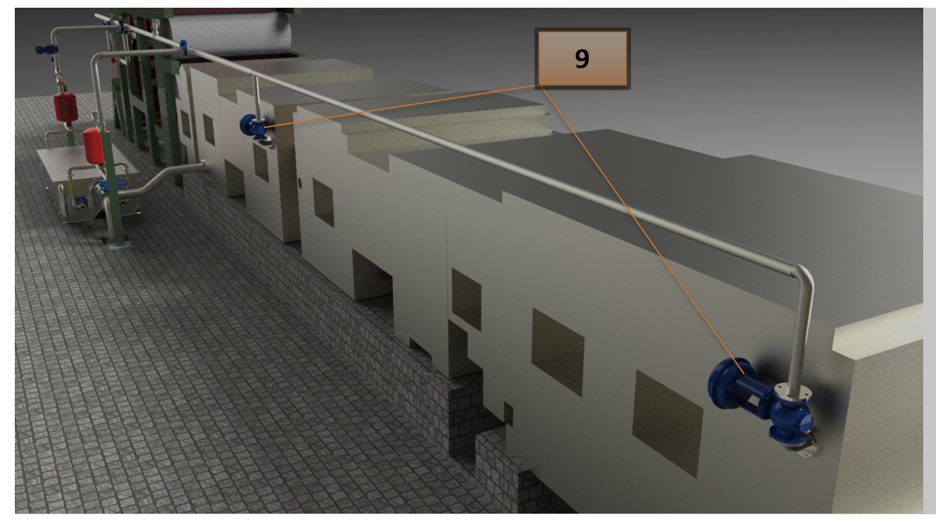
In the redistribution of the pre-heated water to the various sections of the machine, it is important that the proportioning valves for regulating the flow to the same (9) are of the modulating type or, at least, of the low-closing-speed type.
This choice ensures that no water-hammer is induced upstream of the same with benefits for the life duration of the heat exchanger.
E: Effluent water drain
The discharge of the dirty water from the RCR should be immediately lowered to the drain.
If it is necessary to convey it further, please run the piping at ground level to avoid any counter-pressure (even the slightest) to build-up on the exhaust port of the exchanger.