Pozzi Leopoldo RCR EOP - heat recovery system
General info: RHeX & RCR with discontinuous effluent streams
Application
- Home /
- application /
- General info: RHeX & RCR with discontinuous effluent streams
01 INSTALLING POZZI HEAT EXCHANGER IN A DYE-HOUSE WITH DISCONTINUOUS MACHINES
In the presence of a dye-house with discontinuous machines the following situations arise:
· Impulsive discharge flow-rates
· Wide range of temperatures of discharge outflows
· Eventual mixing of cold and hot water in the discharge piping
· Complexity of strategy on how to re-use recovered heat
Our experience in the textile industry, after decades installing heat recovery units in dye-houses especially, dictates the following possible solutions.
02 SCOPE OF RECOVERING HEAT FROM DISCHARGED WATER STREAMS
An efficient heat recovery from discharged dirty hot water in a dye-house may reduce your energy costs to as much as 70%, but in order to achieve such high efficiency and cost-effectiveness, your plant must meet the following requirements:
IMPULSIVE DISCHARGE OUTFLOWS MUST BE MADE CONTINUOUS
In trying to speed up dyeing cycles, every machine is nowadays able to discharge water in a very quick time, since such operation is considered “wasted time” within the dyeing cycle. This means that, normally, a huge quantity of water is discharged in a very limited time. This characteristic does not comply with the need of installing a small and compact heat recovery unit because, if the heat exchanger were so big as to handle an enormous outflow at once, it would work only briefly, a few times a day, with physical dimensions so big and economic costs so high that your investment would not be worth the wile.
The solution, in this case, is to install BUFFER tanks, if not already there. This way, in fact, the tank collects water from discharge piping whenever an outflow occurs, allowing the RCR to use water continuously and with a lower flow-rate.
We shall indicate in another chapter the dimensions and the characteristics of these tanks.
IT IS NECESSARY TO MAXIMIZE WATER TEMPERATURE OF DISCHARGE OUTFLOWS TO BE RECOVERED.
The quantity of heat that can be exchanged in any exchanger may be summarized by
Q= KxSx∆t
Where Q, that is the quantity of exchanged heat equals K, a parameter depending on the efficiency of the type of heat exchanger that you are using, multiplied by the surface of the exchanger and by the difference of temperature between the two streams.
Therefore, the higher the difference of temperature between the two streams, the higher the heat quantity that will be transferred. Furthermore, in order to recover heat effectively, it is extremely important to be able to re-use the recovered heat. This can happen much more easily if you end up with a relatively small quantity of clean pre-heated water at high temperature rather than with a big amount of water at low temperature.
In order to maximize the temperature of dirty discharged water running through the heat exchanger it is important to reduce to a bare minimum or
AVOID EVENTUAL MIXING OF HOT AND COLD WATER IN THE SAME DISCHARGE PIPING.
Modern dye-houses are built with distinct hot and cold water discharges, but most times we come across machines with just one drainage valve that conveys all discharged waters to one channel.
In such cases the best choice is to modify slightly the machines by adding a second drainage valve and another piping (that usually can be easily laid inside the drainage channel) for hot discharge water.
To give you an example, if we were to consider a cotton dye-house that mixes all discharged waters, their temperature couldn’t possibly result higher than 45 °C. On the other hand, if we separate and reduce the flow-rate of the discharge streams, we would have one stream at maximum 30 °C and another stream at maximum 75 °C.
This second hypothesis would allow for pre-heating a smaller quantity of water, close to 60 °C-temperature: the resulting stream is practically ready to use for dyeing, soaping, and hot washing.
03 HOW TO MAKE NECESSARY CHANGES TO OLD-STYLE DYE-HOUSES
The following drawing shows the possible necessary changes to an old-style dye-house in order to achieve the most efficient heat recovery.
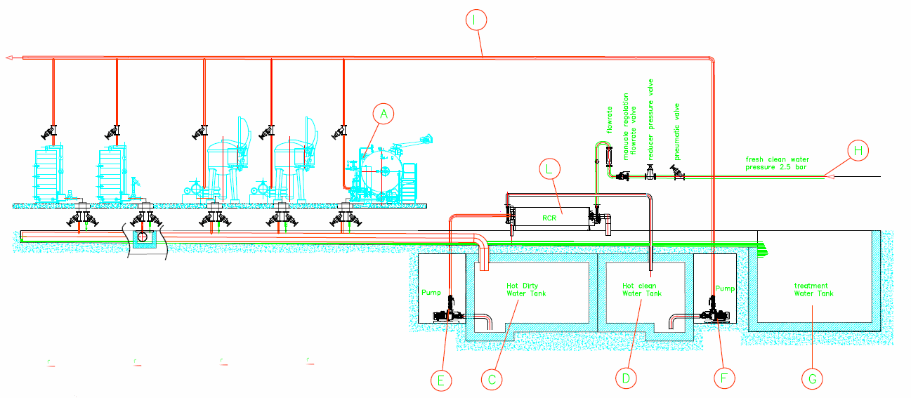
03.01 DOUBLE DISCHARGE VALVES
As we said, it will be necessary to add a drainage valve on the discharge piping without modifying the control panel of the machine (A), since the selection of either hot or cold water valve can be operated by simply putting a thermostat on the discharge port that will activate either valve whenever a discharge is signaled by the machine. For instance, you may decide that water at a temperature higher than 40 °C is conveyed to the hot-discharge piping, whereas water at a lower temperature will be discharged straight into the channel.

As you can see in the above drawing, in order to divide the streams of discharge water without any excavations or modifications to the existing lay-out of the machines, you just need to insert an adequate piping inside the drainage channel, which normally is built along the machines. Very conveniently, you just dismount the single drainage valve, mount a T-connector (B) with two separate discharge valves on the existing drainage port and you divide hot and cold water streams.
03.02 Drainage lines and tanks
The drainage channel will continue to be exactly where it always was, but will drain away only cold water.
The newly in-built piping within the drainage channel will convey hot discharged water to a collecting tank to be built, if not already there (C). The dimensions of this tank shall have to be at least equal to 75% of the total volume of water contained in all connected machines. All this is done in order to guarantee that the impulsive stream of discharged waters is evened out, that is to say it is made continuous.
03.03 Pumping dirty effluents
A small pump in the collecting tank will transfer to the heat exchanger (L) a stream of hot water equaling the evened-out continuous flow-rate resulting from the total amount of discharged liters of water per day divided by the number of working hours of the plant. In the heat exchanger the water stream will run by gravity and will be eventually discharged, once the heat has been transferred and the water cooled off, in the drainage channel for cold water (G).
Care has to be taken in choosing the pump: the effluent will be probably loaded with mechanical impurities so an open-impeller pump will be your best choice.
03.04 Clean water to the exchanger and its circuit.
While the hot water stream runs through the heat exchanger, a counter-stream of cold water will run inside the exchanger rotor. Once heated, this water will be collected in another tank (D), that can either be built underground with concrete or made of fiberglass and left on the outside. The capacity of this tank shall be at least equal to 75% of the total volume of water contained in all connected machines.
A pressurizing unit (F) shall distribute the pre-heated water to be used by machines through piping (I). In case the machines are not provided with two inlet valves for water, it will be necessary to add one for just hot water.
04 HOW TO USE PRE-HEATED WATER
A good heat recovery from hot and dirty discharged water means great energy saving for a dye-house, provided that the dye-house has the possibility to immediately re-use the pre-heated water produced by the heat recovery process.
STARTING ANY PROCESS WITH WATER AT A HIGHER TEMPERATURE
Having collected pre-heated water, all operations that need it can reach the required temperature faster and with a smaller demand of energy. Also the time involved for each cycle is obviously reduced, since there will not be the need of waiting for heating up water in the machine.
SUBSTITUTING COLD PROCESSING WITH HOT PROCESSING OPERATIONS
Instead of using cold water for operations such as washing, the use of pre-heated water results in higher performance during the process. For instance, in the case of repeated washing cycles, the same result will be obtained with fewer washing cycles if you use pre-heated water. In this way, in fact, you not only save on energy, but on cycle time and on water quantity as well.
05. better data collection of recovery
In the previous chapters we have seen how instrumental the economic contribution of a good heat recovery system can be in keeping under control the costs of a modern finishing-house.
For some reason, however, the importance attributed to these systems is always, in a sense, treated as an accessory and not, as it should be, as a fundamental part of the process of energy generation needed to run the factory.
A substantial quantity of heat can be recovered with a relatively insignificant investment.
While a great effort is usually exerted in the correct analysis and accounting of efficiency data on power generation boilers (generation, distribution, consumption), very little or nothing is invested to check the operation of these "auxiliary generators" of energy which account for at least one third of the total thermal energy flow and are disseminated on the various machines.
At best four thermometers are mounted to support a heat exchanger, with no flow detection system and no system of data collection.
This implies that the continuous and constant efficiency control of installations is virtually impossible. A very superficial analysis of their functioning is left to the operators and maintainers and, generally, the reaction time for maintenance calls (that need to be part of the recovery process) is left only to a fixed schedule.
On the contrary, the problem of fouling is of fundamental importance.
Almost every exchanger suffers from the fact that the contaminants present in the waste water may be deposited on its surfaces, progressively decreasing the efficiency up to the point that they become practically unusable. The importance of loss of efficiency varies according to the treated material; it is depending on the operating characteristics of the machine and can affect significantly the cost of a process.
Especially when the machines are used intensively, even a limited variation in the efficiency of recovery systems can result in extremely relevant cost increases. It goes without saying that, if control is no longer entrusted to the discretion of the operators but objectively brought to the attention of those in charge, better economic results should be expected.
With a relatively small expenditure, each of them can be instrumented with an electromagnetic flow-meter, four temperature probes and one calculating instrument for the recovered energy and the efficiency of generated heat exchange.
The software can be designed to cover all the needs of the heat recovery plant, controlling exchangers, levels and pumps.
The same software can keep a log of the taken readings by generating reliable reports of the amount of plant-wide recovered energy.
In practice, this would result in a kit (energy-meter, log-analyzer), to be mounted on each of the recovery exchangers present in the factory, and in the creation of a light network that connects all of them to a central hub that can communicate with a normal PC on which the concentration software can be installed.
The advantages of such an instrument are relevant:
- Obtain objective information on the constant amount of heat re-generated inside the plant.
- Obtain objective information about the need of pro-active service for each monitored heat exchanger.
- Obtain reliable information about the determination of the energy cost of the performed processes.
- Get automatic alerts in case of eventual failure of each of the connected systems.
Given the considerable amount of involved energy, a global improvement of the efficiency of the systems equal to just a few % points can ensure the payback of a system of this kind in a very short time.
06 A typical control system
The instrument is a dedicated control panel to oversee the heat recovery plant with an energy meter and data logger.

The instrument has the dual function of controlling the RCR according to the levels of the dirty water tanks and hot water tank and to acquire the plant operation data.
It is designed to control the full functioning of the heat recovery plant, generating the signals of the dirty water pumps and the movement of the clean water pneumatic valves.
The presence of any abnormalities is indicated by appropriate warning messages and by optical and / or acoustic signals.
The second function is performed by 5 analog acquisition inputs signals: 4 for the input/output temperature of dirty/clean water and 1 for the acquisition of the clean water flow.
Elaborating these data, the amount of recovered energy is calculated.
A straight conversion in the localized currency is possible.
It also logs overtime the amount of preheated water generated (m3) and the recovered energy (Mcal/h).
All data, both analog and digital, are periodically saved on a connected USB memory device to create an history file on the operation of the system and its correct use.
All data is reported in two different screen views on the panel: the real time view and the graph showing the variation of temperature, flow rate and heat flow overtime.
Further elaboration is directly possible as the file can be converted in an Excel file.